Wiring
Motor connection.
Check the nameplate, then confirm rotation before coupling the pump.
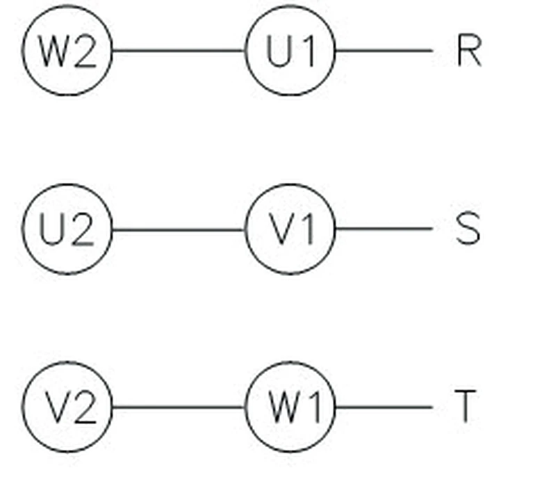
Wiring diagram · catalogue p.34
Pump overview, spring and viscosity data, installation notes, failure table and wiring diagrams.
| Pump type | Internal gear / T-Rotor |
| Fluid | Oils and fuel; lubrication, transfer, hydraulic |
| Viscosity | 20–220 cSt at 40 °C (T-Rotor) |
| Temperature | 80 °C standard; 180 °C with FKM seal (option) |
| Allowable pressure | 0.5 MPa AR1/AR2/ATP-S; 3.0 MPa ATP-HA/H |
| Rotation | 500–2000 rpm AR1/AR2; 300–2500 rpm ATP-HA |
| Ports | PT thread; flange options |
| Mounting | HA / HAB / HAF / H / HF / integrated motor |
| AMTP-MS / MT | 100 / 200 W · 3-phase / 1-phase · IP44 · class B |
| AMTP-HA | 400 / 750 / 1500 W · class B (400 W), F (750/1500 W) |
| AMTP-LN | 200 / 400 / 700 W · 3-phase · IP44 |
| AMTP-HFVB | 1.5 / 2.2 kW · 3-phase · IP44 · class F |
| Voltage | 200/380/415 V 50 Hz; 220/380/440 V 60 Hz |
| Fault | Cause | Measure |
|---|---|---|
| No discharge | Wrong rotation, air in suction, blocked strainer | Check rotation, prime, clean strainer |
| Low pressure | Relief valve open, worn rotor, low viscosity | Adjust relief, replace rotor, check oil grade |
| Noise / vibration | Air in suction, cavitation, misalignment | Tighten joints, raise oil level, align coupling |
| Overheating | Pressure too high, viscosity too high | Reduce relief setting, preheat oil |
| Leak at shaft | Oil-seal worn | Replace oil-seal (NBR or FKM) |
| Motor trips | Wrong voltage, Phase loss, jammed pump | Check nameplate and wiring; free the rotor |
Check the nameplate, then confirm rotation before coupling the pump.
Wiring diagram · catalogue p.34